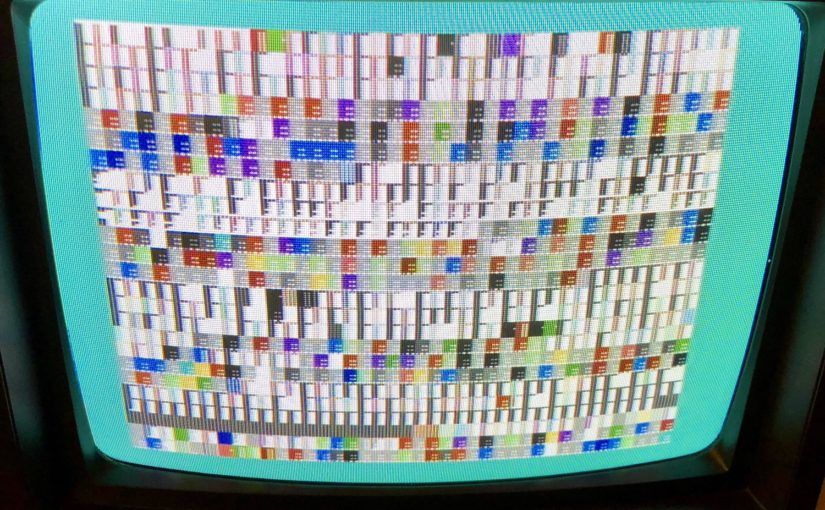
While playing Planet X2, I noticed that some of the text on the bottom right corner of the screen was garbled. I contacted the author of Planet X2 to see if he’s seen this sort of thing before. He suggested that the problemay be due to a memory fault (yep!)
Check out the text in the lower right corner…

My C64 is a breadbox model, which actually has sockecketed chips for things like the PLA, MPU, and SID, so I can replace these easily.
This model, however, has 8 ram chips in total and they were all soldered onto the PCB (I believe most C64 models were like this.) I never did any kind of serious soldering before, so I was hoping I could identify the faulty chip and replace it instead of all of them. Needless to say, I ended up replacing all the chips, but that’s another story…
There are lots of diagnostic tools online, and the ones that are considered must-haves are the DeadTest cartridge (for when you get a black screen) and the C64 Diagnostic cartridge (Rev. 586220). These are useful for identifying problems with your C64 and can even show you which chips need replacement (read lots of documentation online… These tools can give false signals). I bought a Diagnostic Cartridge from eBay and a DeadTest from thefuturewas8bit.com.
The Diagnostic cartridge is very good, but it requires a special harness or else it will give you lots of false signals (you can read more about that in the Diagnostic Cartridge manual). I tried buying a harness on eBay, but was outbid at the last minute. So, I decided to make one, since I thought that it would be a great way from me to practice my soldering skills. It’s a simple enough project to get started with soldering and electronics.
I ended up following the schematic from this page, As far as I could tell, it’s the same schematic listed under C-64 Diagnostic Assembly Kit (CBM 326070-01) on this page. I bought most of the necessary parts from a local electronics shop (Anchor Electronics), but I suppose you can get most of these things from the interwebs (there’s something special about rummaging through electronic components at an old-school electronics shop!)
I put it all together, and it worked great! Well, it worked great once I figured out that I connected some of the wires incorrectly (thanks for helping Alma!). Here’s a partially assembled harness (board still needs to be connected to the user port)

I also followed the recommendation from this page and added an LED to the keyboard header (make sure you add an appropriate LED and resistor to the 5V power). I also added a momentary contact switch to the serial port connector and hooked it up to the reset and ground pins. This way I could use it as a reset button during troubleshooting (see final assembly below).
In any case, I used it to identify the faulty memory chip, and the Diagnostic Cartridge also picked up another faulty chip (4066 @ U28) which I also replaced.

Actually this last chip was not that important since it makes sure the paddles work correctly, and I don’t really care too much about that.
Here’s my C64 system with harness installed and Diagnostic Cartridge running. The screen shows the results of the diagnostic tests and all tests pass (I did not connect the keyboard header here).

Here is a close-up of my (final) harness assembly. I ended up putting everything in D-sub cases and even used a soap box container to house the board.

Here’s the harness connected to the ports of the C64( keyboard header not installed):

And finally, here’s what the whole thing looked like when I was trying to diagnose my C64:
